

this is a place for the things I make and think about : hello,
I'm Q(ns), welcome to my/a qorner of
the/my world (wide web)

mathematician · reader · t(h)inkerer · listener ··· human

The
Qorner

"General gear", desk- and audio-setup, objects, photos, (visual) art, and more from "A StudyRoom of Qns’ Own".

2026-09-14

Note to myself: Write a complete report about my macOS setup and, ideally, overhaul the complete README and documentation of the accompanying GitHub repository as well.

2026-09-12

Note to myself: Write a (reddit) report or make a YouTube video about my Strat. Before: Try to get or make a decal in the "'54 spaghetti logo style", but with:

  • Fender → Modern'59
  • STRATOCASTER → QUSTOM HARDTAIL
  • WITH SYNCHRONISED TREMOLO → MADE IN GERMANY BY QNS
  • ORIGINAL Contour Body → EVOLVING since 2018

Perhaps move this entry to "music".

2026-09-11
Modified Vox AC15C1 amplifier control panel

My only and favorite guitar amp, modded to perfectly suit myself. btw/fyi: yes, I misspelled sepArate on the amp's control panel - and that's ok.

VOX AC15C1 (Revision ISS3c from presumably around 2012) Mods and Repairs/Upgrades

I love this amp. It's been my only amp for a very long time. I made it even better over the years and after doing quite some work recently on it again, I want to share my modding journey of this thing with y'all.

So here are the mods and repairs/upgrades I've done to this thing over the years till today:

Input

  • Made the two channels "jumpable", but a bit different than how they did it in the CCs: I modified the Input-Board to don't short out the tip when nothing is connected to then use an S/DPDT switch to bridge the channels directly at the tip. This way both channels can be bridged with the significant other and all the caps, ferrites and stuff of both lanes are used; the old CCs basically bridged after the Input-Board and therefore ignored the components before that while also making the jumping-feature only available on the Top-Boost-Input. I also permanently attached the Sleeves of both Jacks to the Chassis-Ground and added a common ferrite I had spare to the cable from the Input-Board to the main-PCB.
  • I removed the series input resistor on the normal channel (R1) and of course shorted the two empty holes (0R); and changed the bright cap of the normal channel form 120pF to 94pF, while making it switchable (w/ SPDT). Reason: When using both channels I only want one bright cap in the circuit and the one in the Top Boost Channel sounds good and better than the Normal Channel one to begin with; while I still want the Normal's bright cap available for times I wanna use the Normal channel on it's own in lower volume settings (e.g. Jazz Duo). I just changed it to better quality caps and with a slightly lower value to get a slightly more subtle effect.

Reverb

  • Changed the stock tank (Belton BS3EB3C1B) to an Accutronics 8EB2C1B and then to a TAD 4EB2C1B.
  • Removed the "RCA-Chassis-Terminal" and wired a new and better quality, shielded RCA cable directly to the 3-Pin-PCB-Connectors.
  • Added a classic Tone Control (2nF+B50k) between the Tank-Return and the PCB.
  • Changed R24 (Pre-Gain / Dwell / Decay) from 820k to 330k+B500k. This resistor doesn't only change the Reverb in different ways it also has an effect on the overall Gain, Volume and Noise of the Amp even if the Reverb is turned off. Looking at the schematic makes this behavior pretty obvious and I'm happy with what can be manipulated this way / with this new pot.

Tone Stack

  • Changed the capacitors C20 and C24 to better quality ones with the same value: a "Double Sided Box Type Met Polypropylene Film Capacitor - JFQD" in C24 and a DME one in C20. I believe it made the highs a bit more "hifi".
  • Added a Mids Control: Changed R32 from 10k to B25k; and made that switchable (SPDT: stock (10k) or the new B25k).

Fixed Issues of Later Revisions

  • Grounded the second unused side of U5 (ISS6).
  • Added two caps to V1, presumably for noise-reduction purposes (ISS7).

Upgrades and Repairs

  • Changed the Screen Grid Resistors from 470R 1/2W to 1k 2W and elevated them from the PCB (cf. Lyle/Psionic).
  • Changed R90 and R91 from 220k 1/4W to 227k(3x680) 3/4W(3x1/4W) and also elevated them from the PCB (saw many of them burned in other units over the years).
  • Changed R79 (cathode bias resistor) from 120R 5W (cement-block-style) to 143R(7x1k) 14W(7x2W) (modern metal-oxide, the same as I used for the Screen Grid Resistors) (cf. Lyle/Psionic). Measurements before and after will follow: ... Lyle/Psionic recommended to me https://robrobinette.com/Tube_Bias_Calculator.htm which I used to find out my plate dissipation per tube. I measured the cathode voltage (10.87VDC before, 12.30VDC after), plate voltage (330VDC before, 340VDC after), and the used resistor (120R before, 143R after) and got for the plate dissipation per tube: 13,7W before and 13,3W after (I have 230VAC wall voltage) The "cooling-down" is minimal but I hope at least somewhat beneficial. Lyle/Psionic recommends 12-14W (EL84s want to maximally see 12W, but overpowering them yields the classic Vox power tube distortion and chime and compression and all that, which is why it's essential for the tone to have more than 12W going - if I understand that correctly). Mine was obviously already under 14W, but I thought nearer at 13W or even below that would likely give me a chance to get a bit more longevity out of my EL84s, since they are way more expensive than years ago. What I perhaps do - don't know for sure yet - is just remove one of the seven 1k 2W, which would lead to 167R and would drop the bias even further and pretty surely under 13W, but still above 12W. I think about it and yeah... perhaps will do that. I used what I already had, which is why I chose 7 x 1k 2W instead of additionally ordering 150R 5W; but the good side effect is, that I can get values-in-between this way and by clipping one off I can easily step one step up w/o a bigger soldering/braiding work, which is cool. I don't want to talk about the minimal sound effect I notice by adjusting the bias here, sorry. DID IT: AS EXPECTED I LANDED AT ~167R AND AFTER MEASURING AND USING "ROB" AGAIN I GET 'ABOUT EXACTLY' 12W. TESTED IT FOR A FEW HOURS ALREADY AND IT SOUNDS PRETTY MUCH THE SAME (WAS A BIT "WORRIED" BECAUSE OF THE 12-14W RECOMMENDATION). AND THE TUBES SHOULD BE HAPPY NOW AND SHOULD LAST A LOT LONGER - I GUESS. I KEEP YOU UPDATED.

Miscellaneous

  • Changed the speaker cable from the Greenback to the speaker-PCB to a thick(er) one and soldered it on both sides (like the RCA cable: made a noticeable difference, believe it or not).
  • Added tube cages to V2 and V3 as well as dampeners to the power tubes.
  • For over 10 years I used the following tubes for this amp: "selected" or "gold pin 12AX7" ones for V1, a normal AX7 (JJ) for V2 and an old Sovtek LPS for V3; and matched JJ #7 EL84s for the power tubes. Recently I run a JJ -> EH[since 08.01.26 - slightly smoother high end and a bit less noise in my case] "12AY7 V1" in V1, the old "gold pin 12AX7" in V2 and a normal JJ 12AT7 in V3; while in the power section I landed on matched EH EL84s for now.
  • Lead-Dressing.

Outside

  • Removed the "over 9000" machine and two wood screw from the back-plate; I now just use 3 machine-thumb-screws on critical positions (where the added shielding on the back-plate connects to the chassis for example), which makes working on the amp much easier.
  • Also added a handle where the specification-plate was to easily get this back-plate off, because it always glues itself tight with this dampening foam that is on the chassis.
  • Added a wooden beam-blocker, similar to the ones they had in the past.
  • The VOX Logo fell off years ago and I didn't replace it. It's on my wall now.
  • Removed one corner cap (front-right) to let my Captor X sit there nicely.

Future Plans

  • Try a physical Celestion Blue speaker in this amp, because I love the York Audio VX15 Celestion Blue IR I use daily with my Captor X on this amp. Celestion's official open back Greenback IR (and the 212 Vox one) I also own I don't dislike, but the Blue seems to suit me better - at least the York IR.
  • Change the Bias (R79: from 120 to 150 or something in between) to run the EL84s a bit cooler and therefore let them live a bit longer.
  • Change some more small parts for better reliability (higher wattage etc).
  • Change some stuff on the Tone Cut and Reverb Level pots I have in mind.
  • C32 : 100nF -> 22nF perhaps? [Phase Inverter's "input cap"; change output cap then too? (100nF too)]

If something is missing or comes to mind later, I will edit this post and add the missing bullet-point.
Sound &
Listening

Music writing, recs2, or thoughts about music have a home in here. Also: reports and thoughts about (my own) music gear.

2 warning : double entendre — “rec” means recordings and/or recommendations.

2026-09-12
Modified nut slotting gauge with marked internal components

A discussion of the infamous nut slotting gauge, and how I made mine useful for measuring relief AND string action. I think it fits into this section of the Qorner, it's a maintenance tool and not "room specific gear" per se.. I guess..

Discussion of the infamous Nut Slotting Gauge

I recently bought a "Nut Slotting Gauge" after wanting one for quite some time.

I got mine from Elmer Guitar and paid about 75€ in total, delivered to Germany.

It is meant for measuring nut slot heights, for which it works pretty much perfectly out of the box; regardless of whether you use the 3rd fret capo method or the open string method.

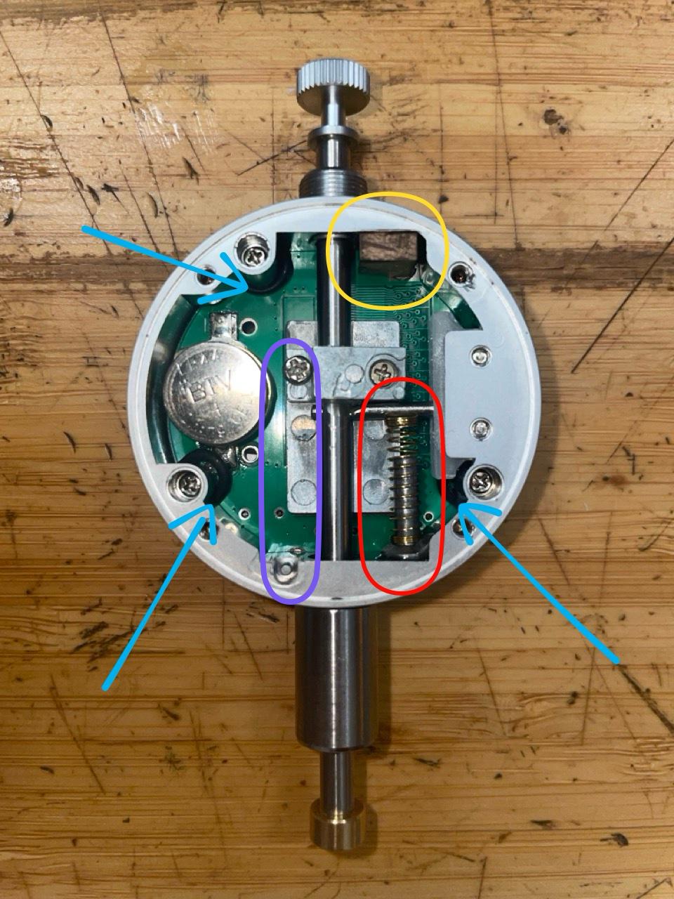
As you can see in the [purple oval in the picture], Elmer already removed the internal down-pulling spring, leaving only the gravity/weight of the plunger assembly itself pushing down onto the strings.

However, I wanted to use this tool for measuring neck relief and string action as well, so I tested it in stock form for these two jobs. The plunger assembly itself weighs about 14.7g (measured using a digital turntable tracking-force scale), which turned out to be a bit too heavy; especially when measuring neck relief, because there the deflection becomes greater then the actual measurement. (X)

The Problem with the Stock Form

Of course, minor deflection isn't an absolute dealbreaker if you just want relative measurements. If a setup feels great and/or is as low as possible without fretting out on the high e string (ones playing style matters here too of course), you can measure that baseline value and repeat it across the other strings for a consistent result. Nonetheless I "wanted more".

To put that 14.7g weight into perspective, let's look at the math for a standard D'Addario EXL110 (.010"–.046") set on a 25.5" scale length at the 12th fret under the stock 14.7g load:

  • High e (.010"): Tension ~16.2 lbs (K ≈ 45.4 g/mm) → 0.32 mm sag
  • B string (.013"): Tension ~15.4 lbs (K ≈ 43.1 g/mm) → 0.34 mm sag
  • G string (.017"): Tension ~16.6 lbs (K ≈ 46.5 g/mm) → 0.32 mm sag
  • D string (.026" wound): Tension ~18.4 lbs (K ≈ 51.5 g/mm) → 0.29 mm sag
  • A string (.036" wound): Tension ~19.5 lbs (K ≈ 54.6 g/mm) → 0.27 mm sag
  • Low E (.046" wound): Tension ~17.5 lbs (K ≈ 49.0 g/mm) → 0.30 mm sag

(Note: Theoretical pure-tension sag numbers; real-world sag on wound strings is slightly higher due to tip compression into the winding).

Now, 0.32 mm might not sound massive if your target action is 1.50 mm, but for a precision measuring tool, it ruins the entire workflow. If you want a real action of 1.50 mm on the high e, you would have to read 1.82 mm on the dial.

Even worse: because string tension and wire gauge differ for every single string, that deflection value changes on all 6 strings. You would constantly have to calculate and subtract a different offset number for every string just to get a simple measurement. That kind of defeats the purpose and ease of having a digital indicator in the first place imho!

And as said above already (X), using it for neck relief readings really isn't possible that way / in stock form.

To make this gauge practically useful (for me) and easy to work with, I thought a counterbalance mod was necessary.

The Solution / Mod

So I thought: Why not add an upward-pushing spring inside the housing, secured and guided by a chopped-off nail, glued in place with epoxy? [red oval in the picture]

After testing several different spring weights and lengths from mechanical keyboard switches I have laying around, my current favorite is a spring from a Gateron Pro Brown switch (~20.5 mm long, ~50g bottom-out).

A couple of other tweaks I made "while being in there":

  • O-Rings & Clearance [blue arrows in the picture]: I added some O-rings between the three housing screws and the display unit: The plunger and its internal "measuring matrix" were sitting too close to the PCB, causing a scratchy feel/movement.
  • Stop-Block [yellow oval in the picture]: I added a small wooden stop-block so the top of the plunger wouldn't get caught on the upper O-ring.
  • 100% Reversible: I made sure all of these mods are completely non-destructive and fully reversible if I ever want to return the gauge to its stock form (the epoxy and nail don't get in the way).

And I can report: It works remarkably well!

I have ~2.1 mm of travel range from the floating/hovering point down to bottoming out, which is plenty of stroke even for my 7.25" radius Strat.

To fine-tune the offset/hovering-point across different guitars, I bought some copper shim washers that fit between the digital indicator gauge and the brass base block: Top Industrieteile Copper Washers They actually measure exactly 0.8 mm ± 0.01 mm, not 1 mm, in thickness and could easily be filed to thinner sizes if needed. Two fit in there nicely while still leaving the set-screw on the brass base working.

How My Workflow Works Now

My workflow is to use (or omit) the copper washers so that when measuring the high e string, the string pushes the plunger at most 0.1 mm to 0.3 mm above its floating/hovering point.

By keeping the plunger right near its neutral floating point on the high e, the net downward load on the string drops to under 1.5g to 2.0g. At this tiny load, string deflection on the high e drops to a negligible ~0.03 mm (~0.001"): visually rock-solid and well within "standard lutherie tolerances".

As you move up to thicker strings, the higher physical string profile moves the plunger further above its hovering point (~0.91 mm higher on a .046" wound E due to diameter alone, plus any gradual action progression). This decompresses the switch spring slightly and adds about 5g to 7g of net weight on the wound strings.

  • Theory vs. Real-World Practice: In "pure mechanical theory", the thick steel core wire of a wound string has exponentially higher flexural bending stiffness (EI ∝ d4), acting like a rigid beam that resists added load. However, in real-world testing, the Low E string still shows around ~0.1 mm of deflection. This is easily explained by real-world factors: e.g. the pointed indicator tip compresses slightly into the softer outer wrap wire, and there is local coil compliance in wound strings that simple beam equations don't capture.
  • Why it still kinda works in practice: As you move from plain to wound strings during a setup, you thoughtfully give thicker strings slightly more clearance anyway (e.g. 1.5 mm on high e vs 1.8 mm on low E) to accommodate their wider vibrational arc. Because you naturally set slightly higher action on thicker strings, this minor ~0.1 mm real-world deflection compensates itself on the go while doing the setup. You just have to keep it in mind.

Conclusion

All in all, I'm quite happy with how this turned out and wanted to share my experience!

In the future, I might experiment with even longer, lighter springs (like 22 mm 30g/35g slow-curve keyboard springs) to flatten the spring force curve even further. But there's a limit: the spring can't be too long or soft, otherwise you lose the essential travel range needed when mounting the brass base.

What do you think about this setup? Do you have other ideas? Let me know!

UPDATE

..on the extra deflection issue: Remember, because the thicker wound strings (D, A, Low E) push the plunger significantly higher up, the Gateron Brown spring decompresses slightly but noticeably. Losing that bit of upward counter-push upwards dropped about +5.5g of net weight onto the Low E, for example (cf. above), causing an extra 0.10 mm of measured string sag: I verified this by comparing measurement results before and after placing a 0.95 mm dense piece of cardboard between the brass base and the fingerboard to simulate the height jump.

The Fix: I surprisingly found out that a 3rd washer (~0.8 mm) actually fits inside/between the brass base and the gauge without blocking the brass base set-screw like I originally feared!

This makes a super easy 2-step workflow possible:

  • Plain Strings (e, B, G): 2 washers (standard setup). Target display reading: 0.20 mm – 0.25 mm of decompression of the spring compared to the neutral hovering position of the plunger. String sag is basically zero (~0.00 mm on high e to <0.02 mm on G).
  • Wound Strings (D, A, Low E): Drop in the 3rd washer. This re-compresses the spring by 0.8 mm, restoring the upward counter-push / compression of the spring and/by canceling out the string height jump. Target display reading here: 0.30 mm – 0.35 mm (of decompression of the spring compared to the neutral hovering position of the plunger).

That 0.10 mm sag on the Low E immediately dropped down to an unnoticeable ~0.01 mm (along with D and A staying well within ~0.01 mm – 0.03 mm), making the gauge practically 1:1 accurate across all 6 strings. No need to buy specialized 22mm springs (considered these: 37g version), just using the Gateron Brown spring from before and a 3rd spare washer did the trick!

Switching steps from plain to wound strings is definitely the sweet spot for 10–46 sets on my guitar's specific radius and fret height, but with tiny adjustments, this method will easily adapt to any guitar setup.

UPDATE 2

A quick note on the original StewMac gauge vs. import units: Regarding the original StewMac unit for context; this one actually uses a much lighter plunger assembly out of the box, so it exerts very little downward force on the string. You can see this tested directly in Paul’s Milehouse Studios video ("The Battle of the Depth Gauges"), where he compares the lighter StewMac plunger to a heavier, standard digital indicator plunger starting at 17:41 (with the side-by-side string deflection test demonstrated from 19:58 to 20:15).

Also, DylanTalksTone has some videos where the deflection seems way less than what I experienced with the un-modded import gauge.

Poems
andor LüRiGG

Some of my Gedichte.

The Science of
Structures & Patterns

Thesis work, mathematical notes, papers, or thoughts on pure mathematics in general.

2026-09-14

Note to myself: Consider sharing my master's thesis here on this website.

2026-08-24

Studying (pure mathematics) at university leads you to learn, how to learn/study
and/or do the lætter "better".
You get to know yourself (in that regard) in great detail: Because everyone learns and consumes differently.
While doing that, you also learn how to ask better questions; because as one knows:
There are no answers really. There are just better questions. More nuanced, if you will. As well there are no clear truths or dogmatism, of course.
But I don't want to get political.
What one learns while being at university, too, implicitly, is to highten their threshold of frustration. To gain the curage to ask "dumb" questions and to lower one's ego. The (big) latter doesn't help (in) anything real or worthy your (life)time btw ..

2026-06-04

This is the CV I use for my recent applications.

page 1 of ? open ↗

webshared
Ranournal

RAndom NOtes & joURNAL : Fragments, observations, half-formed thoughts, and dated entries. Not a blog. Something looser.

2026-09-13

First fact about myself: I REALLY like Penguins 🐧

Dispatches
from Elsewhere

Links, recommendations, things worth reading, places worth visiting on the internet and off.

2026-09-13

My first shared links. In this case: my other qorners on the web.